Controller I/O
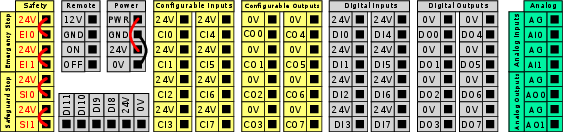
| I/O groups |
You can install the robot according to the electrical specifications which are the same for all three listed inputs. Configurable I/O are I/O configured as either safety-related I/O or normal I/O. These are the yellow terminals with black text.
It is possible to power the digital I/O from an internal 24V power supply or from an external power source by configuring the terminal block called Power. This block consists of four terminals. The upper two (PWR and GND) are 24V and ground from the internal 24V supply. The lower two terminals (24V and 0V) in the block are the 24V input to supply the I/O. The default configuration uses the internal power supply.
|
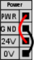
| Power supply default |
In this example the default configuration uses the internal power supply
|
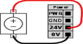
| External power supply |
If more current is needed, you can connect an external power supply as shown below. The fuse is Mini Blade type with maximum current rating of 10 A and a minimum voltage rating of 32 V. The fuse must be UL marked. If the fuse is overloaded, it must be replaced.
In this example the configuration uses an external power supply for more current.
|
| Power supply specification |
The electrical specifications for both the internal and external power supply are shown below.
*3.5A for 500ms or 33% duty cycle.
|
| Digital I/O specification |
The digital I/O are constructed in compliance with IEC 61131-2. The electrical specifications are shown below.
*For resistive loads or inductive loads of maximum 1H.
|